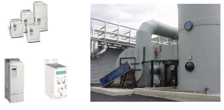
28. Working point regulation by variable speed drive.
The fans often operate at partial flow. For example, on centralized dust suppression, it is not necessary to extract dusty air on non-occupied workstations. To limit the flow of the fan thanks to a butterfly damper installed at the fan proximity is the most expensive solution, because the damper is an extra pressure loss for which the fan is absorbing a power which is not necessary.
We explained (see the article: “Regulation of the working point by inlet vane control”) that the inlet vane control is a more elegant and less energy intensive solution to restrain the flow.
More economical solution consists in the speed regulation of the fan thanks to an electronical variable speed drive: according to a pre-established set point (ex: depression in a pipe measurement), the variable speed drive will adapt the speed of the fan to reach the requested flow.
Example: a fan designed for 1480 RPM, with a max flow of 65000 m³/h on a circuit with pressure loss of +/- 400 mmH2O (point 1):
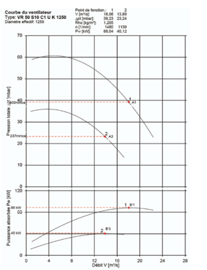
A fan equipped with an inlet vane control totally opened will
absorb 90.3 kW, while absorbing only 88 kW without inlet vane control, because generating an extra small pressure drop even when totally opened.
At partial flow, the new working point will be on the circuit parabola, because the pressure losses of the circuit are
proportional to the square of the speed air (DP = k v²r/2g, this formula is the same form to the equation of a parabola
y=kx²). For example, at 50000 m³/h (point 2), the circuit requesting only 237 mmH2O. If this working point is reach by closing the IVC (inlet vane control) at 50°, the absorbed power will be 63.4 kW. We observe therefore that comparing to a basic damper forcing the fan on 84.3 kW consumption, we realize 20.9 kW of energy saving.
In other hand, if we install a variable speed drive, and regulating the speed to 1139 RPM in order that the fan curve met with the circuit curve at 50000 m³/h, the absorbed power is only 40,12 kW, or an energy saving of 84.3 kW – 40.12kW= 44,18 kW.
The energy saving might be substantial if the partial flows are used frequently.
Let’s suppose in the example below that we are using a fan during 60% of the time at full regime 65000 m³/h and at 40% of the time with a partial regime of 50000 m³/h. We can calculate the energy saving realized after one year, about 8000 h of operation and to calculate the depreciation cost time in regard to a basic damper cost.
| Butterfly damper solution | Inlet vane control solution | Inverter solution | |
| Energy at partial regime/year (60% of time; 8000/year) | 0,6 x 8000 x 84,3 = 404.640 kWh | 0,6 x 8000 x 63,4 = 304.320 kWh | 0,6 x 8000 x 40,12 = 192.576 kWh |
| Energy at full regime/year (40% of time; 8000 h/year) | 0,4 x 8000 x 88,0 = 281.600 kWh | 0,4 x 8000 x 90,3 = 288.960 kWh | 0,4 x 8000 x 88,0 = 281.600 kWh |
| Total energy absorbed/year | 686.240 kWh | 593.280 kWh | 471.176 kWh |
| Extra cost in regard to the butterfly damper: | ± 2.000,00 € | ± 7.500,00 € | |
| Exploitation cost/year (0,06Eur/kWh) | 41.175,00 € | 35.596,00 € | 28.450,00 € |
| Depreciation cost time of the extra cost investment | 4 à 5 months | ± 7 months |
It is quite clear that investing a variable speed drive is very quickly profitable and allows saving important energy cost for the following operation years. This calculation was established for a middle power of 90 kW. Some process requires power much more important (refuse incineration plant, dust suppression installation on the glass furnace, cement manufacture or iron and steel industry), with operations at lower speed. The energy saving are indeed much more appreciated.