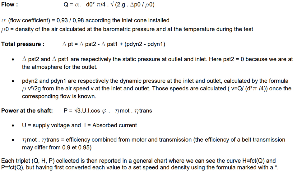
26. Determination of the Aeraulic characteristics of a fan family
When a fan manufacturer answer to a price request for which the requested flow and pressure are important, or when the fans has to be designed according a technical specification file, it is therefore not possible to group all his range in a simple catalog, because it may looks an encyclopedia.
We are then referring to the test of a prototype with an impeller diameter from 800 to 1000 mm. Based on it, we can design several other size machines changing all the dimensions in the same ratio of the main elements of the fan (impeller width, casing…) and keeping the same shape and same blades units, the same casing spiral, … It is clear that several prototypes are necessary, each prototype representing a fan family, in order to answer to the various ratio flow/pressure requested on the market.
According the requested values Flow/Pressure, we apply the basic Aeraulic laws (called also “similarity rules” or “homothetic laws”) in order to find the appropriate size to the requested point (flow/pressure)
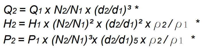
Therefore, without being complicated, in the same fan family, the values flow (Q), pressure (H) and power (P) will be evolving as following, when we switch from an impeller diameter d1 to d2, a rotational speed N1 to N2 and/or a density p1 to p2:
The determination of the prototype curve is done on a bench test defined by a norm describing the bench characteristics and the procedure to apply. Historically, each country was using its own norm, this is why the manufacturer are referring to a DIN, NF, NBN …
As example, we describe here shortly the DIN 24163 which allows testing big fan in the workshop, before delivery, when this test is requested by the client.
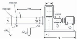
The bench consists in a pipe installed at the inlet of the fan, equipped with a calibrated suction cone and a brace on which are successively stored metal grids with a decreasing mesh size (” twistscreen “) simulating a loss load more and more important. Therefore we can move on the various working points of the fan curve. The measurement of the static pressure Dp0 will give an image of the flow, while the Dpst will give the static pressure at the inlet fan.
Besides these values, the speed, absorbed current, the temperature and the atmospheric pressure will be
measured during the test.
In order to save time and to keep the subject clear, we can apply the following formula for each working point in regard to the specific twistscreen used..