18. Energy saving in the use of centrifugal fans
One of the hot topics in the media is often the energy saving, becoming one of the most important matters for the mankind and our planet. While several industrial major players are trying to decrease the CO2 emissions by several tools (heat recovery boilers, energy production from biomass, cogeneration…) the machines manufacturers (fans, pumps, motors…) are trying to collaborate on this goal, by increasing the energy efficiency of their products.
Electrical motors: improve and standardization of the efficiency
The European directive EuP-lot11, voted in July 2009, define the motors efficiency classes which has to be used in the future. The new norm of efficiency classification for electrical motors (CEI 60034-30) defines the classes as following.
| Characteristics | Description | Definition |
| IE1 | Standard | Comparable to eff.2 |
| IE2 | High | Comparable to eff.1 & EPAct’92 |
| IE3 | Premium | Comparable to EPAct’05 |
| IE4 | Super Premium | Under going project |
The manufacturers are obliged to put on the market motors from 0.75 to 375 kW with a IE2 class efficiency from 16 June 2011. Another norm, the CEI 60034-31 will define the level of efficiency for motors used with a variable speed drive. (We have written in another article about the variable speed drive as the most economical way to use a fan with partial flow).
Optimization of the design for duct pieces to the fan
It is a pity to observe that the efforts engaged to increase some points of the motor or fan efficiency during engineering are destroyed by a misconception of the ducting pieces between the fans and the ducts. “What looks nice to the eye looks nice to the air”, we say. That means we should prefer a bend with a sufficient curvature and to ban any sudden change in the section or in the flow direction, because generator of turbulences and therefor pressure loss.
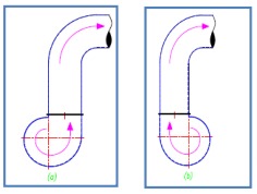
For example, a misappropriate choice for the fan rotational direction is sometimes detrimental for the energy efficiency. In the figure (on the right) according the flow rotational direction in the pipe, we can observe that the flow state is less perturbed in (b) rather than (a). Each perturbation is expressed by new turbulence and therefor by an extra pressure loss with an increase of the absorbed power as final effect.
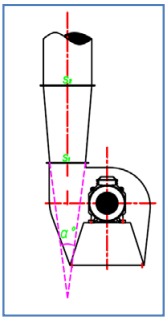
A special care has to be done for the diffusor design installed at the outlet fan. This element used to connect different fan and duct sections, if well designed, will be the reason of a considerable kinetic energy gain to be transformed into static energy, which is the only one used to fight the system pressure drop. This energy regaining can theoretically be calculated as the difference of the dynamic pressures between inlet and outlet diffusor sections:
∆Hdyn = ρ (v2²-v1²)/2g, with ρ is the density of the air and v, the speed at inlet and outlet diffusor.
Indeed, this recuperation is never perfect and will be affected by a loss generated by the air detachment on the diffusor casing called turbulences. We will see in the table hereinafter, the relation between the pressure drop at outlet diffusor, the importance of an angle with limited vertex and the choice of a fan which outlet section is not too different to duct section.
| α | S2/S1 | |||||
| 1.5 | 2 | 2.5 | 3 | 3.5 | 4 | |
| 10 | 0.05 | 0.07 | 0.09 | 0.1 | 0.11 | 0.11 |
| 15 | 0.06 | 0.09 | 0.11 | 0.13 | 0.13 | 0.14 |
| 20 | 0.07 | 0.10 | 0.13 | 0.15 | 0.16 | 0.16 |
| 25 | 0.08 | 0.13 | 0.16 | 0.19 | 0.21 | 0.23 |
| 30 | 0.16 | 0.24 | 0.29 | 0.32 | 0.34 | 0.35 |
| 35 | 0.24 | 0.34 | 0.39 | 0.44 | 0.48 | 0.50 |
∆P= K . v²ρ/2g (mmce) K values
∆P = Diffusor pressure drop (mmce) α = angle at the diffusor vertex
S2= Diffusor outlet section S1= fan outlet section ρ =Density (kg/m³)
v = inlet diffusor speed (m/s)
g = 9.81 m/s² = gravity acceleration
Other system effects may affect the fan curve’s fan:
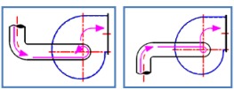
Ex 1 : A bend with a right angle just at the inlet’s fan. This bend makes the air rotating and therefor is a turbulence generator. If the vortex rotational direction is the same as the rotational direction’s fan, the result is a flow decrease, as well for pressure and fan’s efficiency. On the other hand if the rotational directions are opposite to each other, the effect is an increase flow, with the risk of more or less absorbed power increase and therefor a risk of instability.
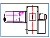
Ex 2 : A damper installed too close to inlet’s fan. The damper will create a distortion of the air flow, generating an irregular load on the impeller. A damper should be installed at least at 5D (D= Ø of the duct) of the inlet flange, in order to allow the air being redistributed correctly before to enter in the fan.
These are several examples of misappropriate configuration but are not limited to. We will be treating in another article some useful advices in the selection of the fans to be used in special systems.